material: epoxy
tool: drill, pencil, pliers, screwdriver
Now that the timer is assembled, we can start making some minor adjustments to attach the cradle to the camera. The description of the shutter lever assembly so far assumes that you are using a Kodak MAX disposable camera. However, it is very easy to adapt the cradle to the shape of other cameras.
9a. Attach a rubber band to the timer tube.
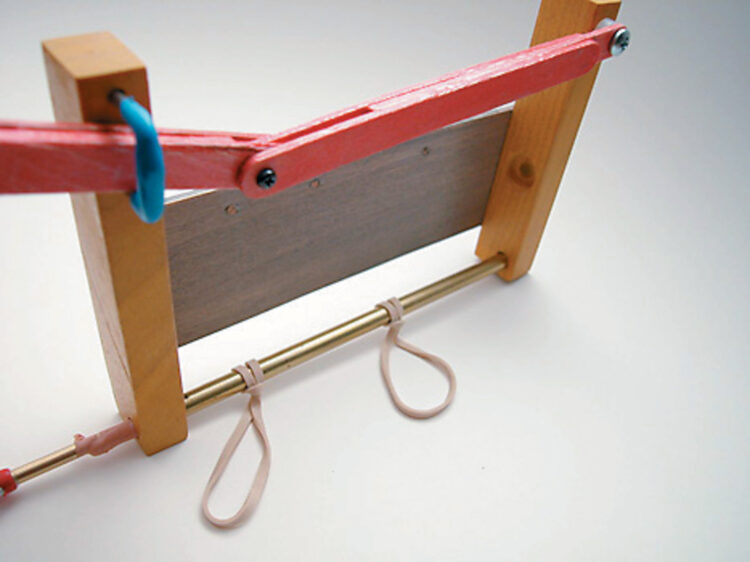
First, prepare two #31 rubber bands. (cormorant) Connect to the brass outer timer tube as shown in the image. Simply wrap the rubber band around the tube, then thread the rubber band back through.
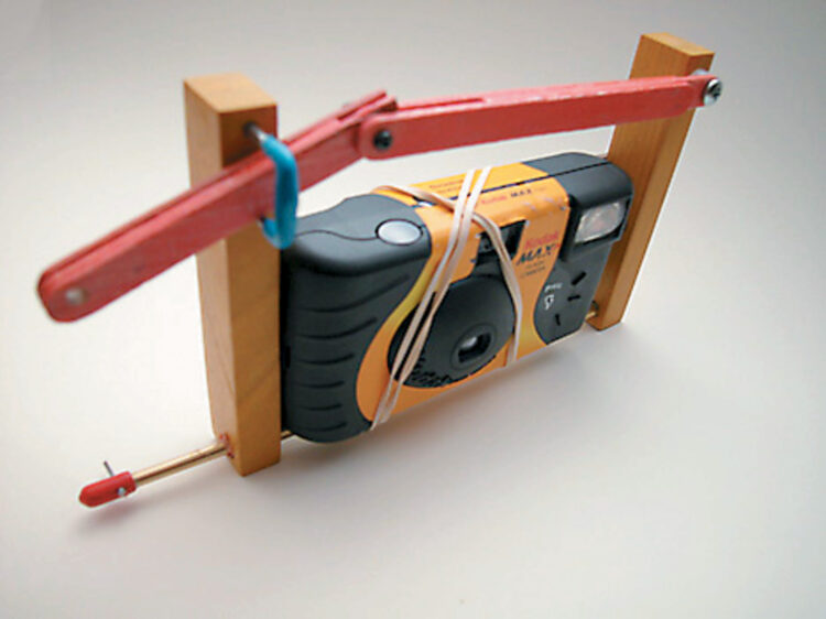
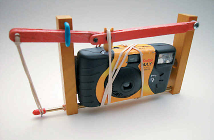
9b. Attach the camera to the cradle.
Keep some blank cameras handy to set up the cradle. Processing labs usually give away some used stuff for free.
Remove the camera and secure it to the cradle using two rubber bands. Allow the bands to cross each other as they pass over the camera and secure them to the pegs at the top of the backplane.
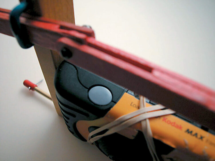
9c. Adjust the shutter lever position.
Nubbins in front and behind the camera.
Let’s examine the relationship between the camera’s shutter button and long shutter lever. If the center gap of the long shutter lever is centered on the shutter button, it’s good. If adjustment is required, this center gap can be moved by changing the size of the nylon spacer. (AG) or installing shutter nubbin (P) It is located on one of the outer surfaces of the shutter lever.
9d. Determine the position of the shutter nubbin.
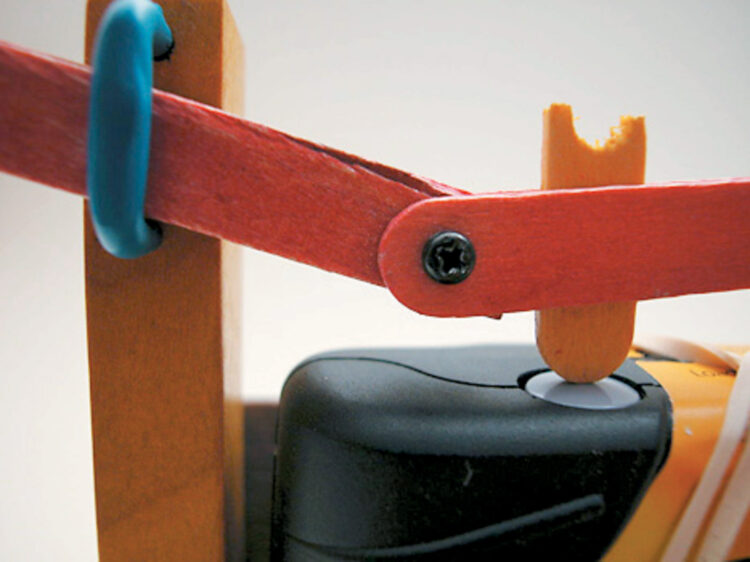
Search for shutternubbins (P)place something made from scraps of a craft stick in the gap in the center of the long shutter lever. Adjust the left or right position of the cradle until it is past the center of the camera’s shutter button. Mark the position of the nubbin on the long shutter lever and the position of the long shutter lever on the nubbin with a pencil.
9e. Attach the shutter nubbin to the lever.
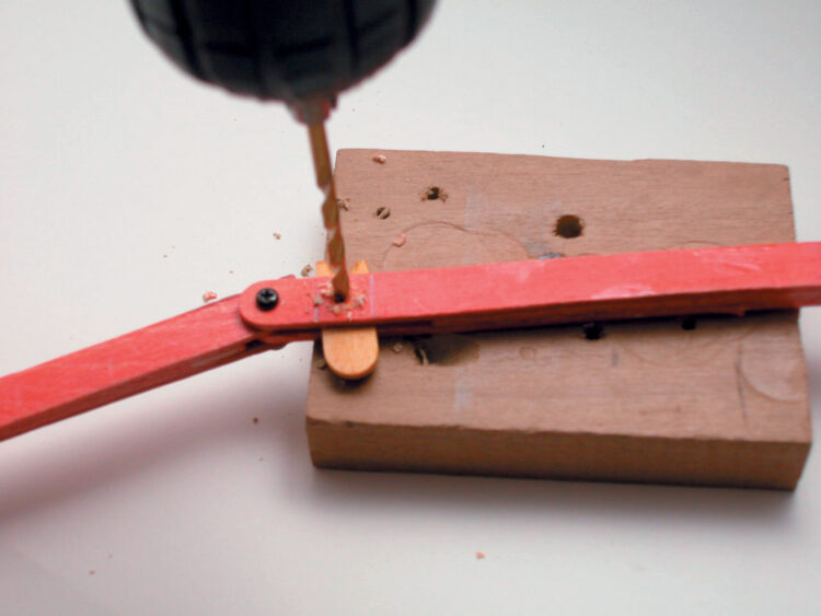
Once the shutter nubbin is in position, remove the shutter lever assembly from the cradle and drill a 7/64-inch diameter hole for the 4-40 bolt. (advertisement) Secure the shutter nubbin to the lever arm.
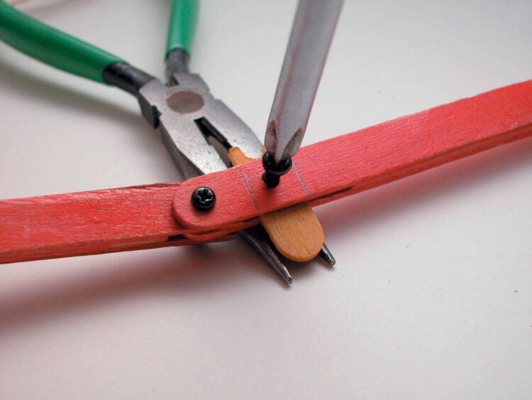
Use the pencil mark guides to make sure the two parts are aligned correctly. Reinstall the shutter lever assembly into the cradle by installing the bolts and tightening them enough to secure the shutter nubbin.
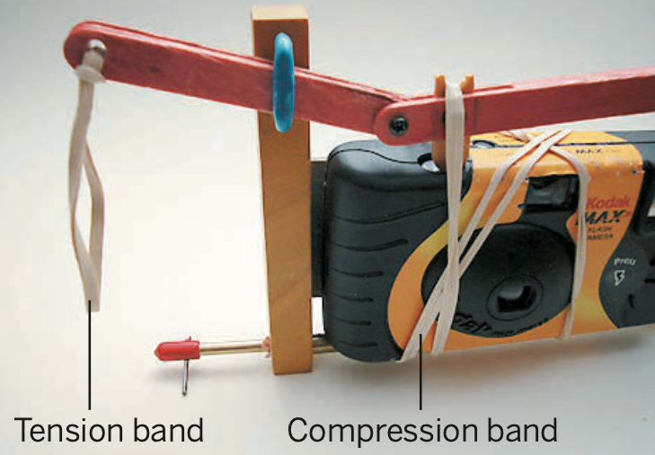
9f. Attach a third #31 rubber band to the “hitch rail” of the outer timer tube and reinstall the camera. Route this compression band through the front of the camera and over the shutter nubbin and secure it to the backplane peg. Attach a fourth #31 rubber band to the end of the short shutter lever. Simply insert it into a 5/32 inch diameter hole and loop it through. This tension band connects to the Silly Putty timer.
9g. It’s time to test the Silly Putty timer. (Insert drum roll sound here.) Follow these steps:
I) Place the test camera in the cradle.
ii) Rotate the inner timer tube release pin to a level with the ground or slightly downward position.
iii) Pull the short shutter lever down and slide the tension/linkage rubber band onto the timer tube pin.
iv) Make sure the shutter nubbin is raised and away from the shutter button.
v) Advance the thumbwheel film advance and cock the camera.
vi) Wait until the timer release pin slowly rotates upwards. If you have a fresh installation of Silly Putty, this may take a long time.
vii) When the shutter is released, you can dance with joy and hug your neighbors. Free!
Initial timer adjustment is primarily a balance exercise. You can adjust the forces within the system. For example, stretching a rubber band a few times loosens it and reduces its propulsion. Inserting more rubber bands at the connection point will effectively shorten the length and increase propulsion. Repeat this type of adjustment until the short shutter lever brings the shutter nubbin directly above the shutter button when the system is cocked. When the tension band slides the timer pin, there should be enough force on the compression band to trigger the shutter.